Creating the Charger
The First Attempt: Spinning Wheel of MagnetsWe do not have the ability to create a charging device as complex and advanced as the one Apple uses, and do not have the capabilities to create a wireless charger either (the iPhone does not support wireless charging, and neither of us own expensive iPhone wireless charging cases of any sort). However, using magnets, copper wire, an old toy, and some smaller wires (with copper wire on the inside), we tried to create a system where we could change the flux and generate an electric current, which could charge the iPhone (the system would be attached to an iPhone charger, which would be plugged into the device).
First, we coiled up the copper wire. Then, using the smaller wires, we attached the large copper wire to the USB portion of the iPhone charger. To do this, we touched the copper wire part that was hanging out of the small wire to that of the large wire, and taped them securely together (to our best ability) with the electrical tape. We put the other end that was hanging out so they each touched one of the contact points on the USB receptor (one on the left side and one on the right side), and secured this with electrical tape as well. Then, we plugged in the 30-pin side of the iPhone charger into a phone, and tried to change the flux so that we could generate a current. We attempted to do this using a spinning wheel of magnets. We taped one bar and one circular magnet to each of the 8 flaps of the wheel (taken from an old children's water toy), then held up the copper coil to it while we spun the wheel. We hoped that this would provide enough change in flux (as induced EMF is equal to change in flux over change in time, or EMF = ΔΦ/Δt); however, it was not successful at producing a charge sufficient for the iPhone to register that it was being charged. Analysis: Part IUpon further inspection, we realized that we were not actually changing the flux in the first attempt, since the distance remained essentially the same and all 8 flaps of the wheel were identical, so the number of B-field lines going through it was the same), which explains our failure.
|
left: close-up of attempt 1 (spinning wheel of magnets)
right: view of entire system in attempt 1 (copper wire connected on each end to smaller wires which are connected via electrical tape to the charger Materials Used
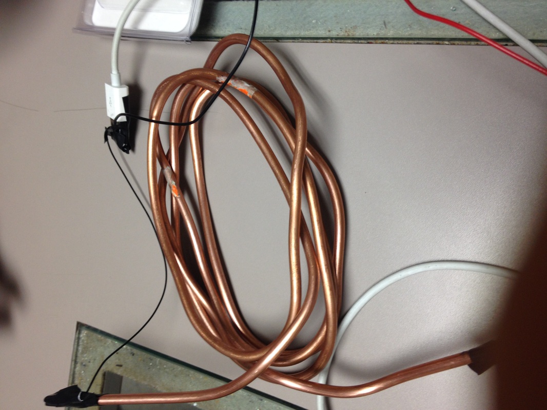
above: picture of the copper wire loop
|


The Second Attempt: Dropping Around the Magnets
|
right: the tower of magnets that we used in the second attempt.
After realizing that we were not even changing flux in the first part, we quickly redesigned how we planned to make it. This time, we tried stacking all the magnets together (to create, in effect, a large stronger magnet), and then lowering the coil up and down around it. This, we thought, would change the flux (as when it is farther away, there are less B-field lines, and also less flux, and when it is closer, it will be higher, so we will get a positive value of ΔΦ and also a positive value for ΔΦ/Δt (EMF). However, when we attempted this, it too failed and we were unable to get the phone to show any signs of detecting a current charging it. We tried moving it side to side at a constant height above (farther away also has less flux, right above has smallest distance and greatest flux), but this did not work either. We even tried dropping the coil straight down (fastest drop - smallest Δt, which theoretically should give us the highest ΔΦ/Δt and thus EMF); however, this also did not work and we unfortunately did not detect any sign of a current charging the device. |

|
Analysis: Part II
However, be believed that the B-field was being changed in the second (as the distance between the wire and magnets significantly increases when we drop it around); thus, we knew that our failure must have come from an additional source. We concluded that the failure on the second time may have been due to:
Regardless of the cause, we still were unable to generate current and charge the phone. Although all of the three are plausible, we believe the third cause (weak magnets) is the most likely, followed by the first (faulty connections). To improve the quality of our charger, we could have tried using a thinner wire that would be easier to wrap around (and wrapped it around many times, since more coils means more charge induced). The iPhone charger is also possible, but it seems like if we had actually generated a significant amount of current, we would have seen it quickly register a current (charging) and then go back off, but this did not happen.
- faulty connections (perhaps when we connected the small/thick copper wires with electrical tape, we may have jostled the wire so that they were no longer touching, and thus would not be able to transfer charge from the thick to thin and then the iPhone charger
- the iPhone charger itself - the charger had been recently malfunctioning a bit (when plugged in, it often registered the charging and then lost it, then re-registered it, etc., resulting in incredibly inefficient charging), however, if the other parts of our attempt had all been correct/sufficient, then we would have seen at least a slight charge (accompanied by a tone or a buzz from the phone) for a small fraction of time
- the magnets we purchased may have been too weak to conduct significant electrical charge - even if we did have all other parts sufficient and correct, the system would have produced so little current that the phone would not have detected it
Regardless of the cause, we still were unable to generate current and charge the phone. Although all of the three are plausible, we believe the third cause (weak magnets) is the most likely, followed by the first (faulty connections). To improve the quality of our charger, we could have tried using a thinner wire that would be easier to wrap around (and wrapped it around many times, since more coils means more charge induced). The iPhone charger is also possible, but it seems like if we had actually generated a significant amount of current, we would have seen it quickly register a current (charging) and then go back off, but this did not happen.
Videos
left: Attempt 2 (failure)
right: Attempt 3 (different method, still a failure)
|
|
|
Calculations
Should we have been able to get the charger working, we really wanted to be able to measure current/voltage and charge time to see how much we could generate from the homemade charger. We had initially attempted to calculate the internal resistance of the charger, however, we realized that would be incredibly difficult for us to do - even if the charger worked - since we do not know what the actual voltage should be (for example, a 12 V battery will have 12 V labeled on it, but ours would not since we made it ourselves). With a fully automatic charger, we may have been able to let it run for the full 100% and see how much it would take to charge, but we could have also seen time vs. amount charged and extrapolated the data to estimate about how much time it would have taken to charge an iPhone to full using our charger (most likely, however, it would have taken much longer to charge than the Apple charger, even if we had been able to get it to work).
We took all the photos and recorded all the videos on this page (no citations)
